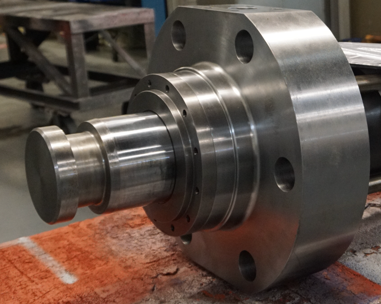
A port is a critical cylinder feature due to standardization, it is not always a critical design consideration. The port allows fluid flow both into and out of the cylinder in order to achieve the linear motion produced by the cylinder. All Sheffer cylinders have a standard port size and location for each bore size and series, but the cylinder designer can select an alternate port type, alternate port size and alternate or multiple port locations.
On pneumatic cylinders standard ports are NPT type ports. On Hydraulic Cylinders, standard ports are SAE O-ring Boss type ports, also referred to simply as SAE ports. SAE ports are manufactured in accordance with SAE J1926-1 specification. While NPT and SAE are the standard ports for Pneumatic and Hydraulic Cylinders respectively, the cylinder designer can select either port type for whichever cylinder they are designing. A third porting option is a four bolt flange port. These ports are manufactured to SAE J518, code 61 specifications, and are typically used on hydraulic cylinders.
Alternate port size is another selection the cylinder designer can modify in their cylinder design. While in most applications the standard port sizes are acceptable, alternate port sizes may be needed to regulate cylinder speed, or adapt to existing plumbing. Smaller ports may be used to restrict fluid flow into the cylinder to keep cylinder speed low, while larger ports may be useful in higher speed applications. If the cylinder designer requires ports that are larger than what can be machined into the head and cap of the cylinder, an oversized port boss will be welded onto the head and cap.
The standard port location is one port on top of the cylinder in each the head and cap. Sheffer considers this to be positions 1 and 5. In order to determine port position look at the rod end of the cylinder and count clockwise around the cylinder with position 1 being at the top on the cylinder head, and 2 through 4 being the other locations on the head, and position 5 being at the top of the cylinder cap with positions 6 through 8 being the other locations on the cap, and position 9 being the back face of the cap.
In designing a cylinder, the designer may determine that the location of the cylinder within the machine dictates ports to be located in non-standard locations. It is possible to select different locations in order to accommodate plumbing needs or other location specific needs. It is also possible to select additional ports. A cylinder designer may select this option to reduce required spare parts such as a right and left hand configuration may be condensed into one design. For example, if the ports need to be positions 1 & 6 for one cylinder and 1 & 8 for an otherwise identical cylinder, a cylinder with ports at pos. 1, 6 & 8 could be used as a replacement for both cylinders.
Porting options allow for a wide variety of customization to a cylinder, but due to standardization, they do not have to be overwhelming for the cylinder designer if the standard ports will suffice.

