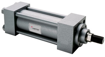
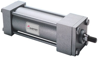
As mentioned in an earlier article, one of the three N.F.P.A. cylinder mounting classes is fixed non-centerline mounts. These mounts include side lug (MS2), end lug (MS7), side flush (MS4), and foot bracket (MS1). In applications where a fixed non-centerline mount is required, Sheffer strongly recommends employing a thrust key plate or dowel pinning the cylinder depending upon the specific mount. This is done to minimize shear loads on the mounting bolts as well as providing a means of cylinder alignment.

The thrust key plate attaches to the cylinder at either the head end or the cap end. It is milled to a close width tolerance and extends beyond the mounting surface of the cylinder by one half of the thrust key plate thickness. The thrust key plate is designed to mate with a milled slot in the cylinder mounting surface of the machine member.
The thrust key plate should be assembled to the cylinder according to the direction of the maximum cylinder load (extend or retract). If the maximum load occurs on the extend stroke, the thrust key plate should be assembled on the cap end of the cylinder. Conversely, assemble the thrust key plate on the head end if the maximum loading occurs during the retract stroke.
The cylinder should only have a thrust key plate on one end or the other. Under no circumstances should there be a thrust key plate on both ends of the cylinder. Keying both ends of the cylinder will not allow the cylinder to expand or contract under pressure and, thus, result in loss of load absorbing capability that the cylinder inherently pocesses.

In the case of side lug mounts, side lugs are sized to accept dowel pin holes in addition to the existing mounting holes. As in the case of the thrust key plate, location of the dowel pins should be in accordance with the direction of the maximum loading, i.e. the cap end for the extend stroke and the head end for the retract stroke. Also as in the case of the thrust key plate, dowel pinning should occur at one end of the cylinder or the other , not both.
Note that if considering keying a fixed non-centerline mount cylinder, exact thrust key plate dimensions, width and length, can be found in the Sheffer “HH” Series and “MH” Series bulletins respectively.

